Project E3
Use Cases of a Multi Energetic System Controller
Basics
The basic assumption for the development of a multi-energy system controller is a district heating of the 5th generation with different decentral connected systems, which are supplied by the thermal grid or feed heat into the grid. The goal is a locally combined operation in terms of heat and electricity. The focus here is on the integration of renewable energies through the decentralised systems. This allows the following thermal operating modes to be defined for the system technology in the buildings:
- Prosumer – feed in the district heating system
- Consumer – obtain heat from the district heating system
- Self-sufficient – without exchange with the district heating system
Regarding to the electrical supply of the properties, a constant exchange with the electrical grid is desired and necessary. So-called stand-alone operation is not considered. This results in the following electrical operating modes:
- Consumer – obtain from the electrical grid
- Prosumer – feed in the electrical grid
In order to implement these different modes of operation with diverse system technologies in interaction with a common district heating system, the development of a multi energetic system controller is necessary. This controller should provide interfaces to the common systems and implement a holistic operational optimisation with the highest possible proportion of locally generated renewable energies.
Definition District Heating System
In the course of energy optimisation and technical development, the temperature levels of heating networks are being reduced. Depending on the temperature level, they can be divided into different generations (Table 1). Within the scope of the project, the use of a 5th generation district heating system is intended, but it should also be possible to integrate systems with higher temperatures.
| District heating | flow temperature | return temperature | |||
| 3rd generation | < 100 °C | 50 … 60 °C | |||
| 4th generation | 45 … 70 °C | < 40 °C | |||
| 5th generation | 5 … 25 °C / < 50 °C | < 25 °C | |||
The name of „5th generation district heating“ does not represent a definition. The following terms can also be found in the literature
- Bidirectional low-temperature heat networks, also anergy networks, anergy heat networks (mainly a term used in Switzerland)
- Cold heat grids (also cold local heating networks or bidirectional cold local heating networks)
- Low temperature grids
- LowEx-heating grids (Low-exergy-heating grids)
Just like the designations, the operating parameters for a 5th generation district heating are not firmly characterised. Depending on the origin and mode of operation, variable definitions exist. In the research project, the 5th generation district heating system is defined as the basis for the use cases as follows:
- heating grid with two pipelines (flow- and return pipe) and directed flow (heat transfer)
- Temperature level approx. ϑ(V FW) ≈ 30 °C
- Combination of different decentral heating prosumers and consumers
Research Subject
On the building side, the requirements of the respective consumers must be met. Depending on the system concept, the temperature levels for heating, by means of radiators or underfloor heating, as well as domestic hot water heating must be taken into account. Table 2 compares the corresponding temperature requirements.
| Consumer | Flow temperature | ||||
| Underfloor heating system | ϑ(V FBH) = 35…40 °C | ||||
| Radiators | ϑ(V HK) = 50…75 °C | ||||
| Domestic hot water | ϑ(V TWE) = 55…65 °C | ||||
The considered buildings are connected to a 5th generation district heating system. The temperature level of this thermal grid is not enough to supply all consumers in the building. Therefore, it is necessary to install a second heating system on the building side, which provides the needed temperature level (for example: domestic hot water). This can be realized in various ways. Within this project difficult use cases are considered and evaluated in terms of technical parameters and feasibility:
- integration of photovoltaic (PV) and a heating rod
- integration of PV and a water-water heat pump (district heating as heat source)
- integration of combined heat and power plant (CHP)
General Requirements
The focus in this project is the development of the multi energetic system controller, which can optimize the operation of the mentioned use cases locally. At the same time, the controller should interact with a controller of a district heating system or the electrical grid with a defined interface. This also creates the possibility to group the decentral plants into a compound and to complement the system supply. It is also possible to supply this completely. An energetic or hydraulic optimization of the thermal grid is not carried out in this project. Only an IT-Interface is developed for this integration. This includes the data protocol, the communication structure and a general data model.
At first, the temperature requirements of the supply structure have to be satisfied, which are specified by the district heating system and the decentral consumption units. Basically, the district heating system is defined as the first heating source of the properties. As a second decentral heating unit (depending on the use case) a heating rod, a CHP-plant and a water-water heat pump will be considered in a compound with the thermal grid.
- Use Case 1: The Heating rod is the second heating unit serves to raise the temperature. There are two energetic boundary conditions: The temperature level of the district heating should not be lower than that in the storage tank. Heat feed-in is possible while the heating element is in operation.
- Use Case 2: A water-water heat pump is the only heat generator (1st heating unit) with the district heating as heat source (Requirement: 5th generation district heating system). In this concept, a feed-in is not expedient, because the heat source and heatsink (of the heat pump) would be identical. The integration of a second heat source or a passive cooling system is possible. This option won’t be analysed in this project.
- Use Case 3: The CHP unit is the second heating unit. It must be possible to supply heat from the district heating system at a sufficient temperature level el. The feed-in of heat (from the CHP unit) is possible.
For each use case, a definition of the possible operation modes is necessary. The following points have to be considered:
- Concept for steering and trading
- decentral optimisation (property) vs. integral operation (as virtual heat and power plant)
- steering/optimisation: decentral/edge services or central/cloud structure
The aim of this research project is a resilient energy supply system. The development of the multi energetic system controller will support this. A resilient energy supply system can be characterized by the following values:
- resistance
- adaptability
- ability to improve or innovate (recovery to adaptation)
In context of resilience, the assessment of an energy supply system has to be considered the aspects of:
- connectivity
- How is the connection between the different units?
- flexibility
- How flexible is the operation management?
- How can individual units react?
- diversity
- How many different sources of energy supply are there?
Consideration of upstream grids
The upstream grids will be considerate with energy balances and temperature levels (district heating). A hydraulic optimization of the thermal grid is not carried out. The focus is a grid-friendly operation of the decentral plants (Consumers and Prosumers) with the highest possible proportion of renewable energies.
- Electrical grid & electricity market
- Regulation according to prices → demand mapping?
- Possibility of considering local demands?
- Is a power consumption in surpluses times possible?
- District heating system
- District heating system as a rotating storage → Which requirements results from this mode of operation?
- Feed-in of heat from electrical power and from heating surpluses through the CHP
Use Cases Overview
The individual use cases are presented in the following overviews. This includes the components, hydraulic schemes and basic objectives as well as boundary conditions. The aim is to develop specific applications for using the system controller.
Use Case 1: PV & Heating Rod
| Components |
|
Hydraulic Schema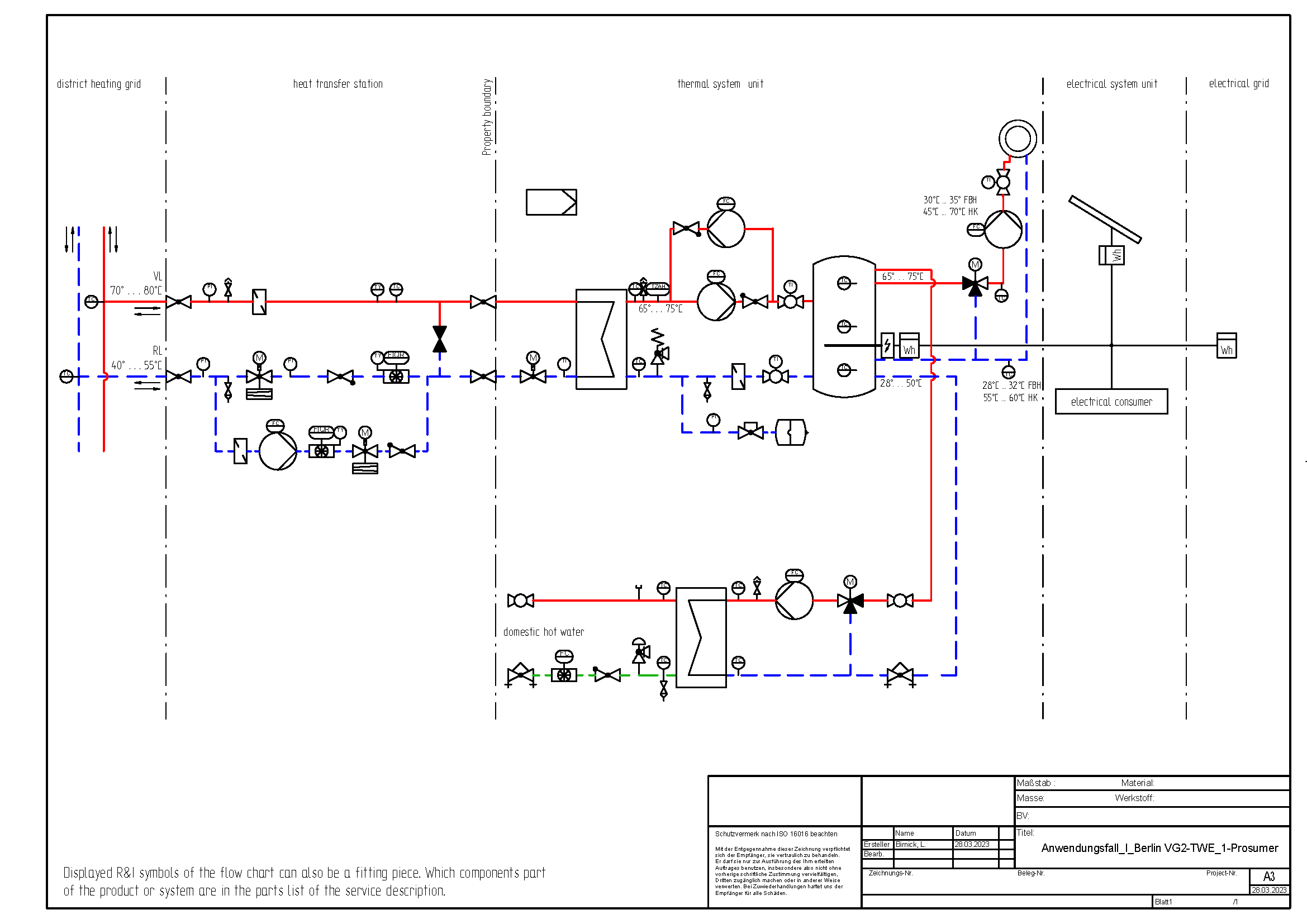 |
|
| Motivation |
|
| Aim |
|
| Mode of Operations |
|
| Boundary Conditions |
|
| Control Concept (local and/or cloud) |
|
| Use Cases / Application |
|
| User |
|
Use Case 2: PV & Heat Pump
| Components |
|
Hydraulic Schema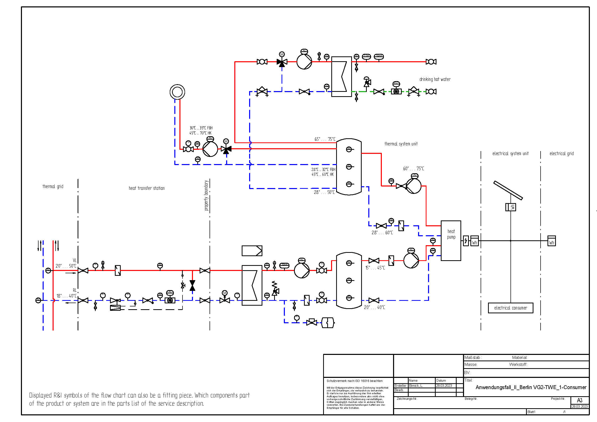 |
|
| Motivation |
|
| Aim |
|
| Mode of Operations |
|
| Boundary Conditions |
|
| Control Concept (local and/or cloud) |
|
| Use Cases / Application |
|
| User |
|
Use Case 3: CHP
| Components |
|
Hydraulic Schema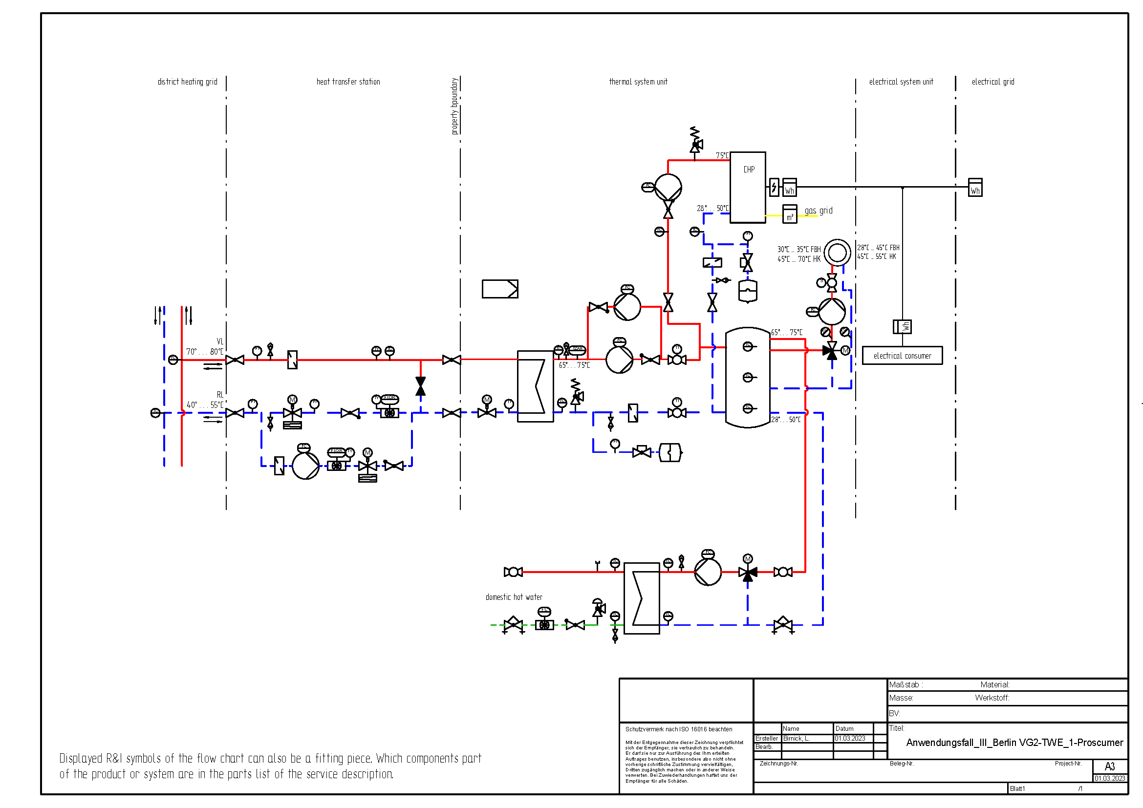 |
|
| Motivation |
|
| Aim |
|
| Mode of Operations |
|
| Boundary Conditions |
|
| Control Concept (local and/or cloud) |
|
| Use Cases / Application |
|
| User |
|
Evaluation of the implementation of the use cases
Overview
The presented use cases have different characteristics in relation to the technical implementation on the building side. The goal of the project is the technical connection of the properties to a district heating system of the 5th generation. Currently, district heating systems with higher system temperatures are predominant. These are district heating system of the 3rd and 4th generation, which are also expected to be operated in this way in the coming years. The possible applications of the use cases in combination with the previously presented different variants of the district heating systems are now compared. The two operating modes prosumer (Tab. 3) and consumer (Tab. 4), including the requirements of different consumers (domestic hot water, type of heating system), are compared. Additionally, the table four shows which heat networks can be used to supply specific building consumers, considering the required temperature level.
| District Heating Use Case |
3rd generation | 4th generation | 5th generation |
| Use Case 1 | (X)1
| (X) |
X² |
|
| Use Case 2 | (X) | X | X |
| Use Case 3 | X | (X) | |
| District Heating | 3rd generation | 4th generation | 5th generation | |
| Use Case | customer | |||
| Use Case 1 | Underfloor heating | X | X | (X) |
| Radiators | X | X | ||
| Domestic hot water | X | (X) | ||
| Use Case 2 | Underfloor heating | X | ||
| Radiators | X | |||
| Domestic hot water | X | |||
| Use Case 3 | Underfloor heating | X | X | (X) |
| Radiators | X | X | ||
| Domestic hot water | X | (X) | ||
1: (X) – possible with restrictions
2: X – unrestricted possible
Causes & Evaluation
In the following, the previously made assessments of the feasibility are briefly justified for the individual use cases. Basically, the defined temperature requirements are used and evaluated, regarding to compliance and technical specifications.
Use Case 1
As a result of the direct connection of the heat storage tank to the heat transfer station, its upper temperature value is in principle the same as that of the district heating network. An additional heating is possible via the electric heating rod in the thermal storage, but the following aspects must be taken into account:
- Cooling of the thermal storage tank must be avoided. Therefore, the supply from the district heating system should operate at a temperature level above that of the storage tank.
- An electrical post-heating with PV-surpluses is only possible for a limited period and for reasons of energy efficiency, it should be avoided to implement a direct electrical heating by electricity purchase from the grid..
As a result, it may be possible to use a 5th generation heating network to supply underfloor heating (ϑV FBH < ϑV FW). The supply of domestic hot water or a heating system with a higher temperature level is only possible with a permanent post-heating. From an energetic point of view, it is not recommended to use an electrical direct heating unit.
A further limiting factor is that the heat consumption in the building must ensure that the heat transfer medium is cooled down to sufficiently low temperatures (ϑHZ < ϑFW) In this case the use with district heating systems of a higher temperature level (3rd or 4th generation) is purposeful.
If PV-surpluses occurs, they can be converted into heat. That’s why it is possible to produce heat surpluses. A feed-in into the district heating system is possible if the temperature in the thermal storage is higher than temperature level of the district heating system (ϑEin < ϑFW). This condition is easier to reach with lower system temperatures.
Use Case 2
In this use Case two thermal storage tanks with different temperature levels are used. The heat pump raises the temperature from a lower level (cold storage tank) to a higher level (hot storage tank, for domestic hot water and heating supply). The low temperature storage tank is connected to the district heating system. Because of that, this use case is useful in combination with district heating systems of the 5th generation. A connection to district heating systems with higher temperatures would counteract the use of the heat pump, so this is not expedient.
The use of PV-surpluses for the heat pump to charge the thermal storage tank can’t be used to feed-in the heat directly into the district heating system. In this case, it would be a feed-in into the heat source of the heat pump. Therefor a second heat source or a hydraulic separation of receive and feed-in would be necessary. This goal is not pursued in the project. A feed-in of heat resulting from waste heat from building cooling is conceivable but is not considered at first either.
Use Case 3
Like use case 1, the hydraulic scheme does not allow a temperature increase when drawing from a 5th generation district heating system. Therefore, the temperature of the thermal storage tank has to be considered because a cooling of the storage tank needs to be avoided. Furthermore, it should be noted with a restrictive effect that the return flow temperature to the CHP should be as low as possible for a high efficiency. A preheating is limited (ϑR KWK < 50 °C).
At the same time (like use case 1), when purchasing from a 5th generation district heating system, the secondary circuit would have to be cooled down sufficiently by the heat consumption. All these aspects limit the heat purchase from a 5th generation district heating system. That’s why a connection to a district heating system with a higher temperature level is more useful.
Reversed to this, a heating supply with a sufficient flow temperature of the CHP could be feed-in into to the thermal grid. In context to district heating systems of the 4th and 5th generation and flow temperatures of the CHP about ϑV KWK > 70 °C is this possible.
Summary
The comparison of the tables 1 and 2 on feasibility shows that none of the use cases can fully cover both feed-in and purchase from the district heating system. This means that no use case can be evaluated as a real prosumer (complete possibility for feed-in and consumption). However, variants are technically useful for separate feed-in or purchase.
Basically, in the use case 1 and use case 3 is no direct temperature increase on the building side from the 5th generation district heating system possible. During heat supply, the storage tank might cool down, as the temperature in the district heating grid can be lower than in the building. This needs to be avoided. On the other hand, this temperature level could be high enough for an underfloor heating system. In contrast, it is useful to purchase the heat of district heating systems with higher temperatures (3rd and 4th generation). It is also possible to feed-in the heat surpluses into district heating systems with lower temperatures (4th and 5th generation).
In use case 2, a purchase of heat from district heating systems with higher temperatures (3rd and 4th generation) is not practicable. Because of a higher temperature level of district heating system, a temperature increase through the heat pump is not necessary. This use case represents the optimal variant for the heat supply from a 5th generation district heating system. A feed-in of heat is in use case 2 difficult to implement, because a second heat source is missing. An option could be the use the heat from a cooling system in the building or a combination with another heat source (e.g. air). This case will not be analysed in this research project.